 EN
EN


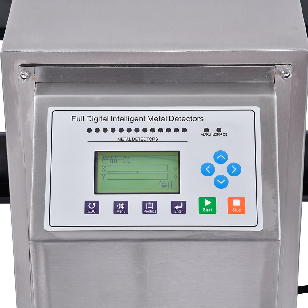
Electrical noise interference represents one of the most challenging operational concerns when deploying an integrated metal detector and checkweigher system on modern production lines. When metal detection and weight verification operate within a single, space-saving module, electromagnetic compatibility becomes critical for maintaining detection accuracy and weighing precision simultaneously. Understanding how noise propagates through shared circuitry, power supplies, and signal pathways is essential for anyone responsible for quality control automation in food processing, pharmaceuticals, or manufacturing environments.
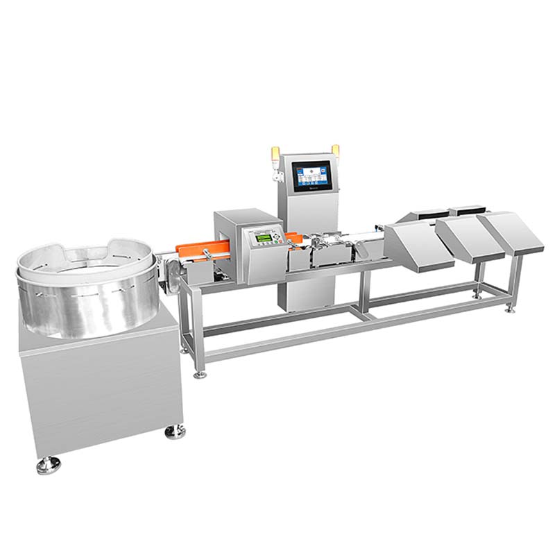
The combination system consolidates two distinct sensing technologies into a compact footprint, which offers significant space-saving advantages. However, this integration also means that radio frequency noise, switching transients, and electromagnetic emissions from the checkweighing load cells can couple into the metal detection circuitry, degrading sensitivity and false rejection rates. Conversely, metal detector oscillators can generate high-frequency noise that interferes with the precise analog signals required for weight measurement. This mutual vulnerability demands careful system design, proper installation methodology, and ongoing operational awareness to maintain both detection and weighing reliability.
Understanding Noise Sources in Combination Systems
Origins of Electromagnetic Interference
An inspection combination that merges metal detection and checkweighing functionality operates two sensitive measurement systems in extremely close proximity. Metal detectors generate oscillating electromagnetic fields at frequencies typically ranging from 50 kHz to 400 kHz, depending on the sensitivity setting and target metal type. These high-frequency oscillations can radiate from unshielded cables and circuit traces, creating ambient noise throughout the inspection combination module. Simultaneously, the checkweigher's load cells convert mechanical weight into electrical signals through strain gauge bridges, which produce millivolt-level outputs that are exquisitely sensitive to any external electromagnetic disturbance.
Power supply circuits, motor drives, and communication interfaces within the space saving design also contribute noise. Switching-mode power supplies operate at tens of kilohertz and generate broadband noise across multiple frequency ranges. Conveyor motors and pneumatic solenoids introduce transient disturbances when activated or deactivated. Cable routing within a compact module leaves little physical separation between noisy power conductors and sensitive analog signal lines, creating ideal conditions for capacitive and inductive coupling.
Noise Coupling Mechanisms in Integrated Designs
Capacitive coupling occurs when electromagnetic fields from high-voltage or high-frequency conductors build up charge on nearby signal wires, introducing unwanted voltage fluctuations into sensitive measurement circuits. Inductive coupling happens when current changes in power cables create magnetic fields that induce voltages in nearby signal loops. Ground plane contamination represents another critical mechanism: when the metal detector and checkweigher share a common ground return path, high-frequency currents from the detector can flow through that shared ground, creating voltage gradients that distort the load cell signal baseline.
Practical Design and Installation Strategies
Shielding and Cable Management
Effective noise mitigation begins with rigorous cable management practices specific to integrated metal detector and checkweigher installations. All load cell wires must be routed in shielded twisted pair cables with the shield grounded at a single point closest to the weighing amplifier, preventing ground loops. Power cables carrying mains voltage or variable frequency drive outputs should be physically separated from signal cables by a minimum of 150 mm, or bundled in separate shielded conduits if parallel routing is unavoidable.
Within the combination system enclosure, an internal Faraday cage constructed from copper mesh or conductive shielding material can isolate the metal detection oscillator circuit from the load cell amplifier. This space saving approach maintains compact dimensions while creating electromagnetic partitioning. All shield connections must terminate to a single point in the module's ground architecture, typically at the main power entry panel. Ferrite toroidal clamps positioned immediately at cable entry points on the inspection combination can attenuate high-frequency noise propagating along external cables before it reaches internal circuitry.
Ground Architecture and Power Distribution
The foundation of noise immunity in any integrated metal detector and checkweigher design relies on a solid, segregated ground architecture. A star-point grounding strategy directs all ground returns to a single reference node, preventing multiple ground paths that create loop areas vulnerable to magnetic field penetration. Power distribution for the metal detector oscillator should originate from a dedicated voltage regulator supplied by a filtered power input, ensuring that detector switching transients do not propagate through the main power distribution to the checkweigher analog circuitry.
Load cell excitation voltage in a space saving combination system should come from a separate low-noise power supply with active filtering, not from the same bus feeding the detector. Checkweigher signal conditioning electronics must be powered by a regulated supply with output impedance below 1 ohm at the frequencies where noise problems are most acute, typically 100 kHz to 1 MHz. Digital circuits in the metal detection signal processor can tolerate slightly noisier power, allowing them to share a second regulation stage downstream of the analog supply.
Operational Testing and Optimization
Baseline Noise Measurement and Diagnosis
After installing an integrated metal detector and checkweigher system, baseline noise characterization establishes a reference for future troubleshooting and identifies optimization opportunities. With the metal detector powered but the conveyor stopped, measure the checkweigher output signal stability over five minutes using an oscilloscope or data logger, recording peak-to-peak noise amplitude and spectral content. Repeat the measurement with the detector transmitting at full amplitude, then with the combination system running empty conveyor cycles, and finally under full production load. Comparing these baseline measurements reveals whether specific operational states introduce problematic noise.
Frequency domain analysis using an oscilloscope's FFT function or a portable spectrum analyzer identifies dominant noise frequencies. If peaks appear at the metal detector frequency or its harmonics, shielding and grounding require review. If noise appears at switching supply frequencies, power supply filtering needs enhancement. This diagnostic approach transforms noise reduction from guesswork into systematic improvement, ensuring that modifications to the space saving inspection combination actually address root causes rather than symptoms.
Calibration and Sensitivity Tuning
The metal detector sensitivity within an integrated metal detector and checkweigher system should be set only as high as required for the target contamination protocol, never maximized for theoretical detection range. Higher sensitivity increases both the signal amplitude and the oscillator frequency, typically generating more noise that radiates into the checkweigher circuitry. Field adjustments of detector sensitivity performed after installation allow operators to find the minimum gain necessary for reliable detection while maintaining checkweigher measurement stability. Combination system designers often provide a sensitivity range of 50 to 100 percent; operating routinely at 60 to 75 percent often provides optimal noise-to-signal balance.
The checkweigher's filter time constant should be set to average signal fluctuations caused by product motion and vibration, but not so long that it masks genuine weight changes. A filter constant between 100 and 300 milliseconds typically tolerates baseline noise while responding quickly to weight variations in space saving inspection combination installations. Advanced signal processing algorithms in modern checkweigher firmware can reject noise spikes that exceed statistical confidence bounds, further improving stability without sacrificing response time.
FAQ
Why does metal detector noise specifically affect checkweigher accuracy?
Metal detectors generate continuous high-frequency oscillating magnetic fields to detect conductive or ferromagnetic targets. These oscillating fields induce small voltages in the load cell signal conduits and in the checkweigher amplifier input stages. Since load cells produce only millivolt-level signals proportional to weight, any externally induced voltage becomes a significant fraction of the measurement signal, causing calibration drift, repeatability errors, and false reject decisions. The combination system compresses both technologies into a single module, minimizing physical distance between noise source and sensitive measurement point, making the coupling effect more severe than in separate standalone devices.
Can proper grounding alone solve electrical noise problems in a combination system?
Grounding is absolutely foundational but rarely sufficient by itself. A properly designed star-point ground architecture with segregated power supplies eliminates many noise paths, but electromagnetic coupling through air and through common impedances can still propagate interference into sensitive circuits. Combining grounding improvements with physical shielding, cable separation, filtering, and load cell excitation isolation creates defense-in-depth against noise, with each layer contributing to overall immunity. Most successful integrated metal detector and checkweigher installations employ all of these strategies simultaneously rather than relying on any single technique alone.
What are the first diagnostic steps when an inspection combination shows noise-related measurement errors?
Start by turning off the metal detector and confirming that checkweigher measurement stability improves dramatically. If noise disappears, the detector is the source and hardware modifications to shielding, power separation, or grounding are needed. Next, examine cable routing visually and by tracing with your hands to identify where signal cables run close to power cables. Measure the potential difference between ground points at different locations in the combination system; if voltage variations exceed a few millivolts between supposedly bonded locations, a ground connection is likely high-impedance or missing. Finally, capture oscilloscope waveforms of both the metal detector transmitted frequency and the checkweigher analog output to confirm whether noise peaks correlate with detector frequency components, guiding targeted remediation efforts.