 EN
EN


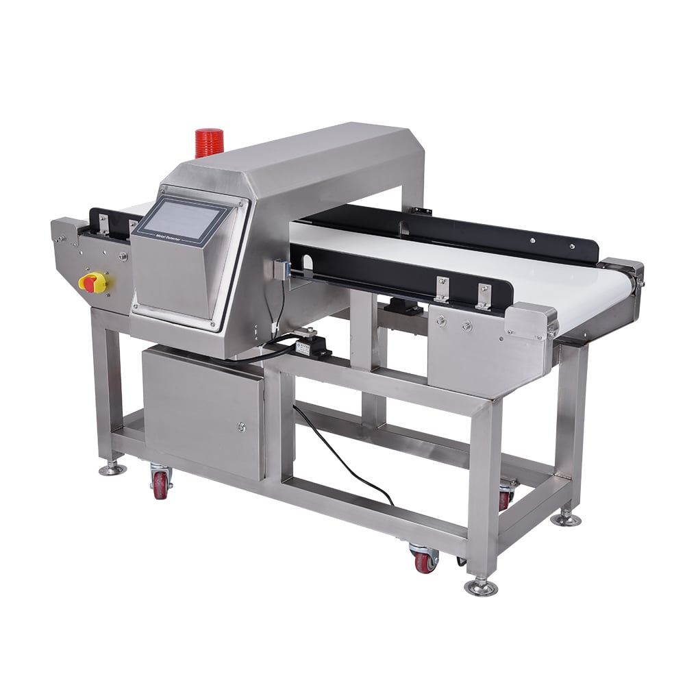
Sensor coil shifts represent one of the most frustrating alignment failures in modern inspection systems, yet many facility managers lack the practical knowledge to diagnose and resolve them quickly. When the internal coil assembly inside an industrial metal detector drifts from its calibrated position, detection sensitivity drops sharply, false positives multiply, and production throughput suffers. Understanding the root causes and systematic correction methods is essential for maintaining reliable bulk inspection performance across pharmaceutical, food processing, and manufacturing environments.
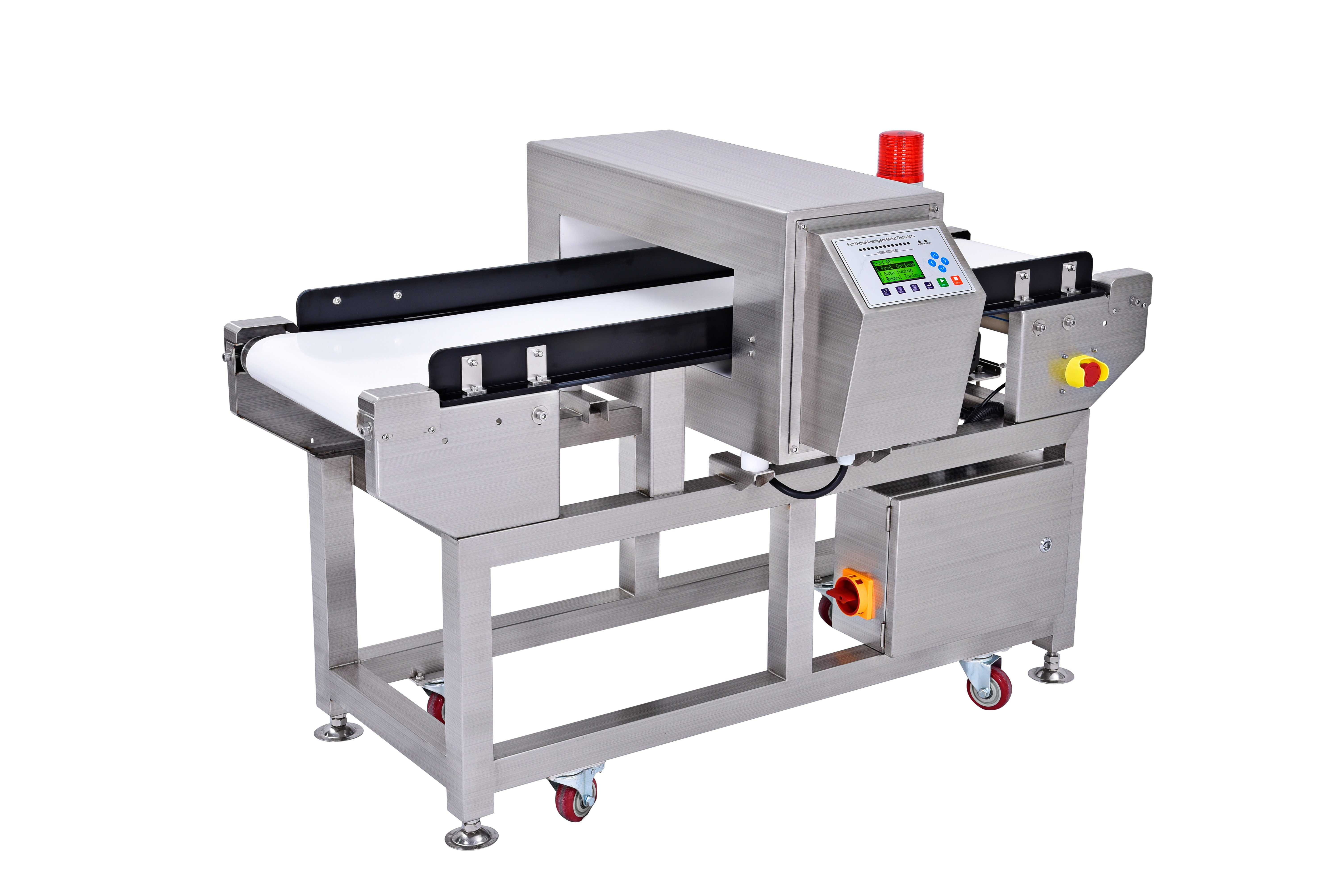
A factory metal detector relies on precise electromagnetic field geometry to detect metal contamination reliably. Even minimal coil displacement disrupts this carefully balanced field topology, reducing effective sensing range and creating inconsistent response patterns. This guide walks through the diagnostic sequence, common mechanical causes, and restoration procedures that restore your heavy duty metal detector to full operational sensitivity without requiring manufacturer service calls or extended production stoppages.
Understanding Coil Shift Mechanisms and Detection Impact
How Coil Displacement Affects System Performance
The transmitter and receiver coil assemblies in an industrial metal detector operate as a coupled electromagnetic system. When these coils shift relative to their mounting references, the symmetry of the magnetic field pattern breaks down. A sideways drift of even 2–3 millimeters can reduce detection sensitivity by 15–25 percent, particularly for smaller or lower-conductivity metal particles. This degradation appears as increased product throughput without corresponding contaminant detection, creating hidden liability and regulatory compliance gaps.
Coil shifts typically originate from mechanical loosening, vibration-induced settling, or material creep under the weight of repeated cycles. In a factory metal detector used for bulk inspection operations, thousands of products pass through the detection window daily. This continuous physical stress can gradually loosen fastening hardware, compress cushioning materials, and migrate mounting brackets sideways. Your heavy duty metal detector may still power on and display readings, but the actual magnetic field geometry no longer matches the system's calibration baseline.
Recognizing Coil Shift Symptoms Early
Early detection of coil misalignment prevents cascading performance loss and extends equipment service intervals. Look for gradual sensitivity drift—where you must manually increase gain settings week-over-week to maintain the same detection threshold. Inconsistent false positive rates across different shift times often signal coil shift, as the detector compensates unevenly for the misaligned field. Additionally, phantom alarms triggered by nonmagnetic materials or erratic baseline wandering indicate that the internal electromagnetic reference has destabilized due to coil displacement rather than external electrical noise.
Temperature-dependent performance changes—where the industrial metal detector behaves differently after warm-up—also suggest mechanical shift. As electronics warm up, thermal expansion can either mask or exacerbate an existing coil misalignment, producing time-dependent sensitivity swings. If your bulk inspection system shows these patterns, coil position verification should become an immediate maintenance priority rather than a deferred activity.
Diagnostic Procedures for Identifying and Measuring Coil Displacement
Visual Inspection and Physical Measurement Techniques
Begin with a powered-down physical inspection of the detector head assembly. Look for visible gaps between coil mounting brackets and their reference surfaces, or colored witness marks that show movement. Many factory metal detector designs include alignment witness marks applied during manufacturing. If these marks no longer align with the mounting structure, the coil has definitively shifted. Measure the displacement carefully using precision calipers or feeler gauges, recording both horizontal and vertical offset values.
Check all fastening bolts, set screws, and locking washers around the coil assemblies. A loose fastener often precedes visible coil shift by several weeks. Tighten any slack fasteners by hand first to feel resistance, then gradually increase torque to the manufacturer-specified level using a calibrated wrench. Do not over-tighten, as excessive force can crack ceramic coil formers or compress internal damping materials unevenly. Record which fasteners required re-tightening, as pattern repetition may indicate design weakness requiring design modifications to your heavy duty metal detector installation.
Electromagnetic Field Mapping and Calibration Verification
Advanced troubleshooting uses field-mapping instruments to visualize the actual electromagnetic pattern generated by the industrial metal detector. These include gauss meters, search coils, or software-controlled field analyzers that measure field strength at multiple points around the detection window. Compare the measured field map to the system's documented baseline profile. Significant asymmetry or off-center field concentration confirms coil shift and quantifies the direction and magnitude of displacement.
Calibration verification involves running standardized test samples—typically small metal discs of known mass and composition—through the detector at fixed speed. Record both the signal amplitude and timing relative to the trigger threshold. In a properly aligned system, identical samples produce nearly identical responses. Varying responses indicate that the electromagnetic field is nonuniform around the detection window, pointing directly to coil misalignment rather than electronic drift. This empirical approach provides objective confirmation before undertaking corrective assembly work on your bulk inspection equipment.
Systematic Correction and Realignment Procedures
Mechanical Restoration and Fastener Optimization
Once coil shift is confirmed, systematic mechanical restoration begins with complete fastener verification across the coil mounting assembly. Remove each bolt, inspect the threaded holes for deformation or debris, and replace any bolt showing corrosion or thread damage. Use stainless steel or lock-threaded replacements in high-vibration environments where the factory metal detector operates. Apply medium-strength thread-locking compound to prevent rotational loosening while permitting future disassembly without damage.
Reassemble the coil assembly using a stepped torque procedure: hand-tighten all fasteners first to establish even pressure, then incrementally increase torque in diagonal or cross-pattern sequences to distribute clamping force uniformly. Heavy duty metal detector designs often employ precision dowel pins or alignment bushings in addition to bolts. Verify these positioning elements remain properly seated and undamaged. If dowel pins show wear or corrosion, replacement with hardened stainless pins ensures repeatable alignment across future maintenance cycles.
Re-Baseline and Functional Validation
After mechanical correction, the industrial metal detector must be re-baselined and functionally validated before returning to production. Power the system and allow a full warm-up cycle, then run the standard test sample protocol again. Compare new response data to both the pre-correction degraded baseline and the original manufacturer specifications. Response consistency should improve noticeably, with signal variance reduced by 50 percent or more in properly corrected systems.
Conduct a full sensitivity sweep, gradually reducing detector gain until marginal metal test samples just trigger the alarm threshold. Document this sensitivity setting and compare it to the baseline value stored during initial commissioning. A successful coil shift correction typically restores sensitivity within 5–10 percent of the original commissioning baseline. If sensitivity remains significantly degraded, deeper investigation into coil winding integrity or electronic component drift may be necessary. Document all correction parameters, test results, and fastener torque values in your maintenance log. This creates a performance reference that helps predict future coil shift timing and supports predictive maintenance planning for your bulk inspection operations.
FAQ
What are the most common causes of coil shift in industrial metal detector systems?
Coil shifts most commonly originate from vibration-induced fastener loosening, thermal cycling stress, and material creep under sustained mechanical pressure. In factory metal detector environments, daily vibration from conveyor motion and product impact gradually unsettles mounting bolts and compresses damping materials. Temperature fluctuations cause differential expansion rates between coil formers and metal mounting frames, generating internal stress that slowly shifts alignment. Less frequently, manufacturing defects in coil former symmetry or improper initial assembly can predispose systems to drift. Heavy duty metal detector designs with robust fastening systems and higher-grade damping materials resist coil shift more effectively than budget alternatives.
Can coil shift be prevented through maintenance, or is it inevitable over time?
While some degree of mechanical settling is inevitable in any detection system, strategic maintenance dramatically reduces coil shift frequency and severity. Quarterly fastener verification, systematic vibration isolation, and proper mounting to stable base frames prevent the vast majority of premature shifts. A well-maintained industrial metal detector can operate 2–4 years between significant re-alignment work, compared to 6–12 months for neglected systems. Regular baseline testing also catches early signs of drift before sensitivity degradation becomes operationally significant, enabling planned maintenance rather than emergency shutdowns.
How does coil shift impact bulk inspection reliability in regulated industries like pharmaceuticals and food processing?
In regulated environments, coil shift creates both performance risk and compliance documentation problems. As detection sensitivity degrades from shift-induced misalignment, contaminant pass-through rates increase, raising product safety and regulatory liability. Factory metal detector performance records become unreliable if the system's actual sensitivity diverges from its documented calibration baseline. This discrepancy creates audit findings and requires corrective action documentation. Bulk inspection operations in pharmaceutical and food processing must maintain continuous performance records demonstrating that the industrial metal detector remained within validated sensitivity windows. Systematic coil alignment monitoring and correction procedures ensure these compliance records remain accurate and defensible during regulatory inspections.