 EN
EN


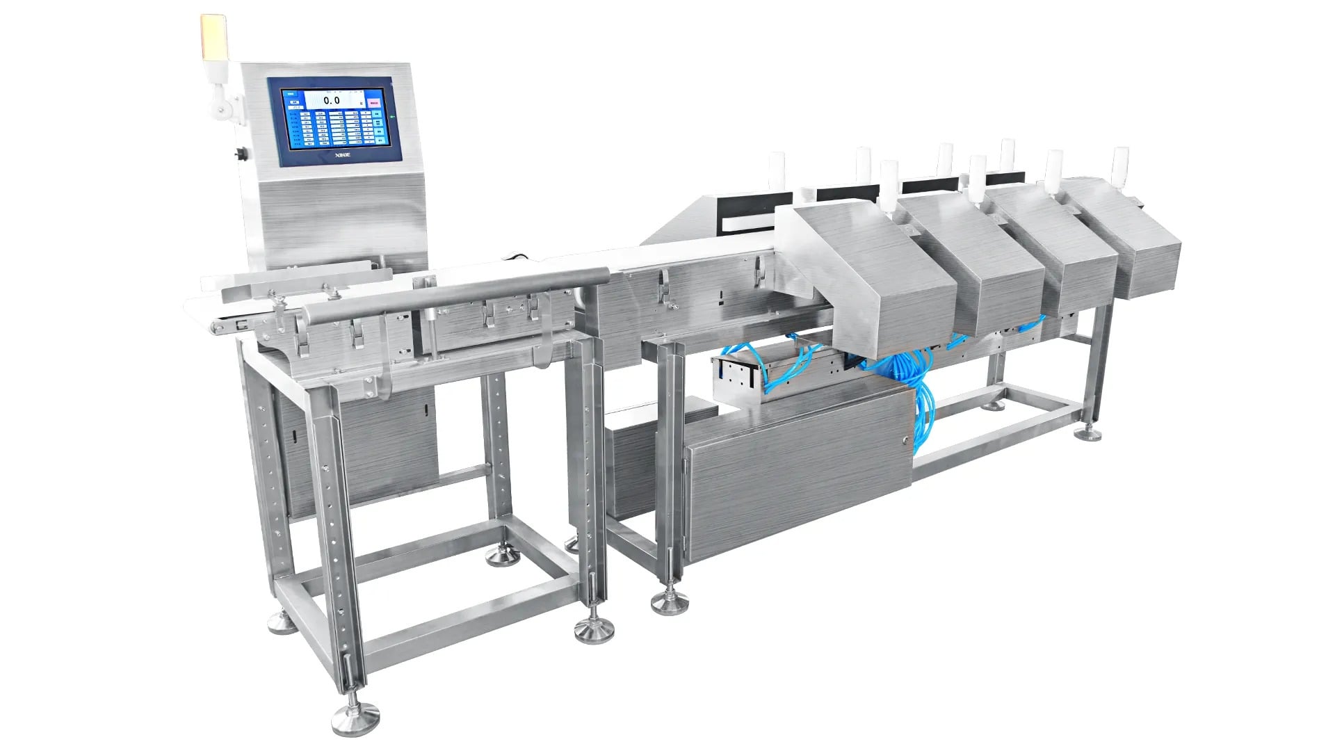
Single HMI communication faults in an integrated metal detector and checkweigher system can halt production lines and compromise product safety. When your combination system experiences connectivity issues between the human-machine interface and the detection hardware, rapid diagnosis becomes critical. Understanding the root causes of these faults and implementing systematic troubleshooting procedures will minimize downtime and restore operational efficiency.
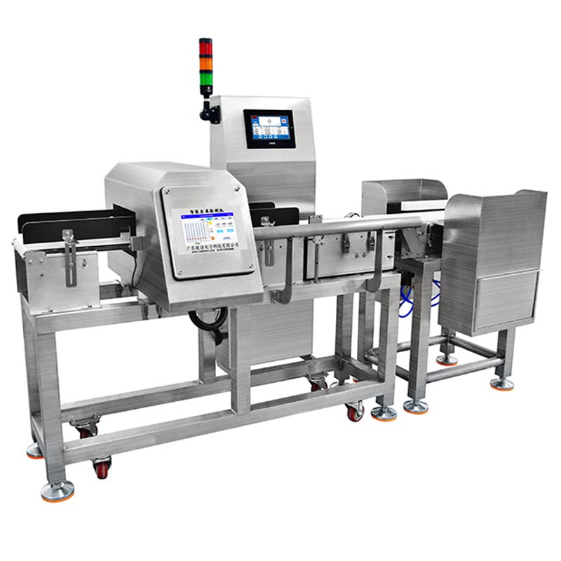
An integrated metal detector and checkweigher represents a space saving solution that combines two critical inspection functions in one platform. The HMI serves as the central control point for both detection and weighing operations. When communication between the HMI and the combination system fails, neither function operates reliably, making troubleshooting urgent and necessary.
Understanding Communication Architecture in Combination Systems
How the Integrated Metal Detector and Checkweigher Communicates
Your integrated metal detector and checkweigher relies on serial or network protocols to transmit data between the HMI touchscreen and the sensor modules. The communication pathway includes signal transmission from metal detection sensors, weight sensors, and motor controllers back to the central processor. Any interruption in this chain causes the HMI to display timeout errors, offline indicators, or inability to read sensor data.
The combination system architecture typically involves multiple communication layers. The inspection combination hardware communicates through Ethernet, RS-485, or proprietary fieldbus protocols depending on the manufacturer design. The HMI interprets these signals and translates them into visual feedback and operational commands. Understanding this layered structure helps identify at which point the communication fault originates.
Common Communication Pathways and Failure Points
In a space saving integrated configuration, the sensor modules mount directly to the main frame with short cable runs. This proximity reduces electromagnetic interference but creates dependency on connector integrity. Loose connectors, corroded terminals, and cable pinches represent the most frequent communication failure sources in combination system layouts. Additionally, firmware version mismatches between the HMI and the hardware module cause protocol incompatibility and communication rejection.
Systematic Troubleshooting Procedures for Single HMI Faults
Physical Connection Verification Steps
Begin troubleshooting by inspecting all physical connections on your integrated metal detector and checkweigher system. Examine the main communication cable connecting the HMI unit to the central processor module. Look for visible damage, crimped sections, or partially disconnected connectors. Power down the system before disconnecting any cables to avoid electrical damage. Reseat each connection firmly by unplugging and reseating the connector with deliberate pressure until you feel a positive click.
Check the terminal blocks where the HMI communicates with the combination system sensors. Corrosion on brass terminals prevents reliable signal transmission even when connections appear physically seated. Use a small wire brush or pencil eraser to clean terminal contacts gently. For corroded terminals on the inspection combination module, request replacement terminal blocks from your equipment supplier. Document the cable configuration with photographs or sketches before disconnecting anything to simplify reassembly.
Network Configuration and Protocol Validation
Modern integrated metal detector and checkweigher systems often use Ethernet-based communication. Access the HMI settings menu and verify the IP address, subnet mask, and gateway settings match your facility network configuration. Ping the hardware module IP address from a networked computer to confirm network layer connectivity exists before assuming a space saving combination system fault.
For RS-485 or serial communication protocols, validate baud rate settings on both the HMI and the hardware module. Mismatched baud rates prevent the combination system from interpreting transmitted data correctly. Common baud rates include 9600, 19200, and 38400. Consult your system documentation to identify the correct setting. Also verify parity settings, stop bits, and flow control parameters match exactly between devices. Even a single incorrect parameter causes complete communication failure in these inspection combination configurations.
Firmware Updates and Compatibility Management
Outdated firmware versions between your HMI and the integrated metal detector and checkweigher hardware module frequently cause communication rejection. Contact your equipment manufacturer to confirm both devices run the same firmware revision level. Space saving combination systems sometimes receive component updates that introduce firmware incompatibility. Download the latest firmware revision for both the HMI interface and the hardware module simultaneously to ensure protocol compatibility.
Document the current firmware versions before updating. Create a system backup if your HMI supports backup functionality. Perform firmware updates during scheduled maintenance windows to avoid unplanned production interruptions. After updating, the combination system should reinitialize automatically. Monitor the first operating cycle closely to confirm communication establishes without errors. If communication fails after a firmware update, revert to the previous version and contact technical support.
Advanced Diagnostics and Error Code Interpretation
Reading HMI Error Logs and Diagnostic Screens
Most integrated metal detector and checkweigher systems include diagnostic screens that display real-time communication status. Access the maintenance or diagnostics menu on your HMI touchscreen to reveal detailed error codes. These codes identify whether the communication fault originates from the metal detection module, the checkweighing module, or the central processor. Write down the exact error code and timestamp for reference during troubleshooting conversations with technical support.
In space saving inspection combination designs, check the LED indicators on the hardware module itself. Green lights typically indicate normal operation, amber indicates warnings, and red indicates faults. Count the LED blink patterns if your combination system uses blink codes to communicate status. Many manufacturers provide blink code interpretation charts in their technical documentation. These visual indicators often reveal communication problems faster than scrolling through HMI menus.
Using Testing Equipment for Signal Verification
A multimeter helps verify voltage presence at key connection points on your integrated metal detector and checkweigher system. Measure voltage across communication cable pairs to confirm power delivery reaches the hardware module. Typical communication voltages range from 5 volts to 24 volts depending on the specific combination system design. If voltage reads zero or significantly below specification, a cable break or connector fault exists between the measurement point and the power source.
For advanced troubleshooting, use a USB logic analyzer or oscilloscope to view actual communication signals on serial or fieldbus communication lines. These instruments reveal whether the HMI transmits data correctly and whether the space saving inspection combination module responds appropriately. Signal analysis requires technical expertise but provides definitive proof of whether communication attempts occur or fail completely. Many equipment manufacturers offer remote diagnostic support where they can observe these signals through data logging features.
FAQ
Why does my integrated metal detector and checkweigher show communication timeout errors?
Timeout errors indicate the HMI sent a command to the integrated metal detector and checkweigher hardware module but received no response within the expected timeframe. This occurs when cables have loose connections, baud rates mismatch, firmware versions differ, or the hardware module lost power. Start by checking physical connectors and verifying power reaches all modules. If the combination system still times out after connection inspection, move to firmware verification and configuration validation steps.
Can a space saving combination system communicate over both wired and wireless connections?
Most space saving inspection combination systems operate exclusively over wired connections for reliability and industrial hardening requirements. Wireless communication introduces latency variability and interference risks unsuitable for metal detection and checkweighing precision. Some newer HMI systems support wireless remote monitoring displays, but the core integrated metal detector and checkweigher hardware still requires stable wired communication. Consult your manufacturer's specifications to confirm supported communication methods for your particular combination system model.
How often should I perform preventive maintenance on communication connections?
Inspect the communication connections on your integrated metal detector and checkweigher monthly or quarterly depending on your facility environment. Dusty, humid, or corrosive environments increase connector deterioration rates for your inspection combination system. Before the start of each production shift, visually verify cable connections remain seated and undamaged. Replace connectors showing green corrosion immediately to prevent future communication faults in your space saving combination system. Establish a preventive maintenance schedule specific to your facility conditions.